2.3.5. Definition of Band Offsets (zincblende)
This section explains how band offsets are evaluated in nextnano++. It begins with showing connection between parameters used in database{ …{ conduction_bands{} } } (see valence_bands{} and conduction_bands{}) and band energies at their extrema. Then, various band alignments and exemplary interpolations, with and without strain, are presented. All plots are computed for materials at 300 K.
Schematics of band structure in vicinity of the \(\Gamma\) point is shown in Figure 2.3.5.1. Energies of band extrema in the case of lack of strain are depicted with gray lines and labels, while the parameters stored in database are plotted in black color.
plot.png)
Figure 2.3.5.1 Band structure of freestanding (red solid lines) and compressively strained (pink dashed lines) in vicinity of \(\Gamma\) point.
The starting point of defining the offset in nextnano++ is the average valence band energy \(E_{v,av}\) which can be modified by using bandoffset attribute. Formally, it is defined as the average energy of three top valence bands
where \(E_{hh}\), \(E_{lh}\), and \(E_{so}\) are energies of heavy-hole, light-hole, and split-off bands at \(\Gamma\) point, respectively. In the case without strain, \(E_{v,av}\) is located \(\frac{1}{3}\Delta_{so}\) below the top of the valence band. The spin-orbit splitting energy \(\Delta_{so}\) and the energy gap at the \(\Gamma\) point \(E_{g}^{\Gamma}\) are available through attributes delta_SO and bandgap. Depending on the group to which the bandgap attribute belongs to, it may refer to energy differences involving conduction band minima at \(\Gamma\), \(L(\Lambda)\), or \(X(\Delta)\) points (lines).
One has to specify all three parameters (including Varshni’s parameters for temperature dependence of \(E_{g}^{\Gamma}\) and other gaps) for every material of interest to define whole band alignments. Our database contains and provide space to contain these parameters and related bowing parameters for all specified materials listed here.
It is important to keep in mind that offsets of bands are not easy-to-measure parameters, so their values are typically provided by simulations within ab-initio approaches. Therefore, for fine simulations, we advise to always verify all the material parameters and adjust them. Our database already consists of numerous published material parameters resulting in the offsets as visible in Figure 2.3.5.2 and Figure 2.3.5.3.
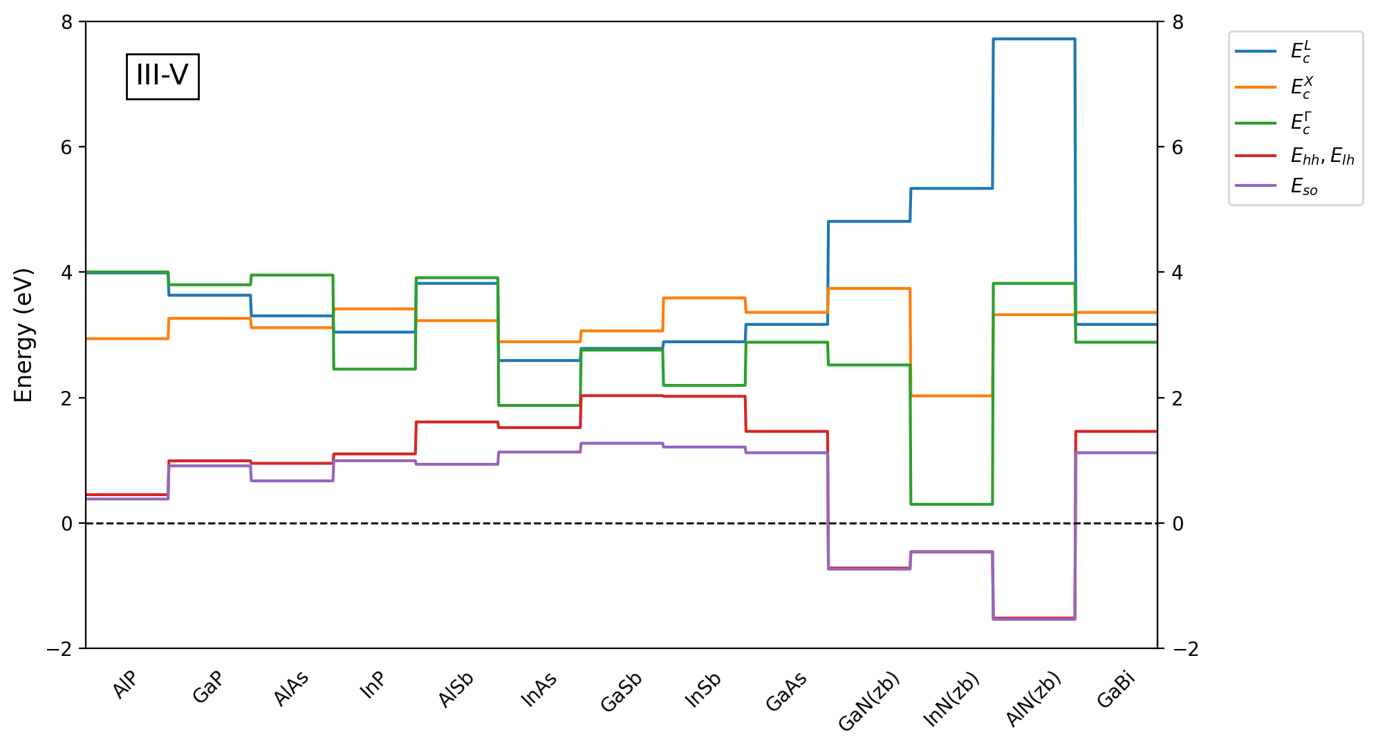
Figure 2.3.5.2 Band offsets of III-V zincblende binary compounds calculated with default parameters predefined in our database
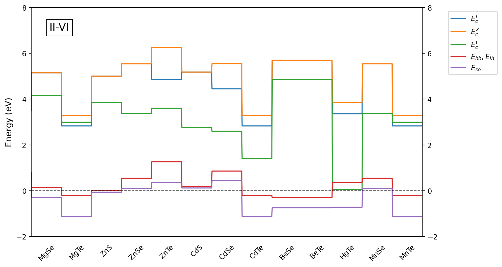
Figure 2.3.5.3 Band offsets of II-VI zincblende binary compounds calculated with default parameters predefined in our database
To obtain band alignments for alloys, the three parameters (\(E_{v,av}\), \(\Delta_{so}\), and \(E_{g}^{\Gamma}\)) are properly interpolated and further used to provide minima of conduction bands (\(E_{c}^{\Gamma}\), \(E_{c}^{X}\), \(E_{c}^{L}\), …) and maxima of valence bands (\(E_{hh}\), \(E_{lh}\), and \(E_{so}\)) according to formulas:
\[\begin{split}\begin{aligned} E_{c}^{X} &= E_{v,av} + \frac{1}{3} \Delta_{so} + E_{g}^{X}\\ E_{c}^{L} &= E_{v,av} + \frac{1}{3} \Delta_{so} + E_{g}^{L}\\ E_{c}^{\Gamma} &= E_{v,av} + \frac{1}{3} \Delta_{so} + E_{g}^{\Gamma} \\ E_{hh} = E_{lh} &= E_{v,av} + \frac{1}{3} \Delta_{so}\\ E_{so} &= E_{v,av} - \frac{2}{3} \Delta_{so} \end{aligned}\end{split}\]
Attention
The parameters in the database, such as \(E_{v,av}\), \(\Delta_{so}\), and \(E_{g}^{\Gamma}\), are defined for freestanding bulk crystals (without any strain), while final band energies, like \(E_{hh}\), \(E_{lh}\), \(E_{so}\), \(E_{c}^{\Gamma}\), do include strain effects if proper conditions are met. Therefore, for example, in strained structures one should expect that \(E_{g}^{\Gamma}\ne E_{c}^{\Gamma} - E_{hh}\) and \(E_{g}^{\Gamma}\ne E_{c}^{\Gamma} - E_{lh}\).
Plots of resulting band energies for three chosen alloys (\(\mathrm{Ga_x In_{1-x} As}\), \(\mathrm{Al_x Ga_{1-x} As}\), and \(\mathrm{In_x Al_{1-x} As}\)) within full mole fraction ranges are shown in Figure 2.3.5.4. As visible for \(\mathrm{Al_x Ga_{1-x} As}\), content-dependent bowing parameters are also available in our routines. All the parameters necessary to compute strain effects are included in the algorithm in the similar manner. They are interpolated first and then applied to evaluate energy shifts of band energies.
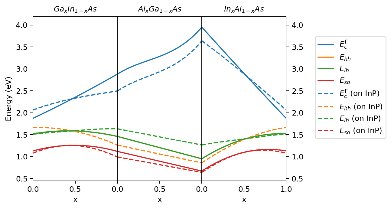
Figure 2.3.5.4 Interpolated band edges of \(\mathrm{Ga_x In_{1-x} As}\), \(\mathrm{Al_x Ga_{1-x} As}\), and \(\mathrm{In_x Al_{1-x} As}\) without strain (solid lines) and strained as grown on [1 0 0] plane of InP (dashed lines).
Last update: nn/nn/nnnn