Resonant tunneling diode (RTD)
This tutorial is based on the following publications: [GreckPhD2012]
The following input files were used:
RTD_PhDthesis_PeterGreck_ballistic.negf (MSB calculation of Fig. 8.2 of [GreckPhD2012])
RTD_PhDthesis_PeterGreck.negf (MSB calculation of Fig. 8.2 of [GreckPhD2012])
These example input files demonstrate how to calculate the current in a Resonant Tunneling Diode (RTD). In RTD, quantum mechanical effects are essential. We use the same structure as outlined in Section 8.2 of [GreckPhD2012].
We perform two simulations:
RTD_PhDthesis_PeterGreck_ballistic.negf - calculation without scattering (ballistic calculation)
RTD_PhDthesis_PeterGreck.negf - calculation including scattering
The RTD structure consists of 48 nm GaAs.
In the central region, there are two 4 nm wide AlGaAs barriers enclosing a 6 nm wide GaAs well. These two AlGaAs barriers are separated by a 4 nm intrinsic region.
Outside the barriers, the structure is doped with a concentration of 1017 cm-3.
The barrier height was taken to be 0.156 meV.
The temperature is set to 150 K.
The grid spacing is 1.0 nm.
Further material parameters used are:
effective mass: 0.067 (GaAs) and 0.0795 (Al0.15Ga0.85As)
static dielectric constant: 10.89 (GaAs) and 10.4808 (Al0.15Ga0.85As)
LO phonon energy: 0.035 eV (GaAs) and 0.0373 (Al0.15Ga0.85As)
The following figure shows the calculated current-voltage characteristics. It corresponds to Fig. 8.2 of [GreckPhD2012].
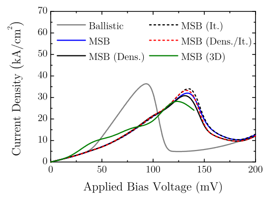
Figure 4.7.5 Fig. 8.2 of PhD thesis of Peter Greck
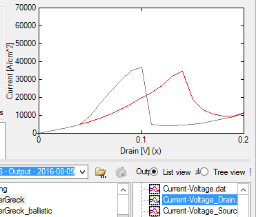
Figure 4.7.6 Calculated current-voltage characteristics of the ballistic calculation (gray) and the calculation including scattering (red).
The peak current density is at 100 mV for the ballistic calculation but is shifted to 140 mV for the calculation that includes scattering.
The file that is plotted is called Current-Voltage_Drain.dat.
The relevant lines are gray (Ballistic) for the ballistic calculation and blue (MSB) for the calculation including scattering. The peak current density of the ballistic calculation is reached at about 100 mV where the chemical potential of the source contact is aligned with the lowest quantum well state. However, this result is physically wrong. This is due to the fact that a ballistic calculation neglects any kind of incoherent scattering. In a realistic device the carriers do not ballistically reach the RTD. Instead, a bound state is formed by the triangular shaped potential in front of the RTD and inelastic scattering processes lead to a capture of carriers within this state. Since the energy of this bound state is lower than the chemical potential of the source contact, the alignment with the RTD resonance is realized at higher bias voltages. For the calculated RTD, the peak currenty density is shifted from 100 mV to 140 mV.
Results
The following figures shows the conduction band edges (BandProfile/BandEdge_conduction.dat) together with the
local density of states \(\rho(x,E)\) (
DOS/DOS_position_resolved.avs.fld)electron density \(n(x,E)\) (
CarrierDensity/CarrierDensity_energy_resolved.avs.fld)current density \(j(x,E)\) (
CurrentDensity/CurrentDensity_energy_resolved.avs.fld)
at the peak current densities of 100 mV (left figures, ballistic calculation) and 140 mV (right figures, calculation including scattering). Note that the peak current density of the ballistic calculation (100 mV) deviates from the peak current density (140 mV) of the calculation including scattering.
Local density of states \(\rho(x,E)\) plots:
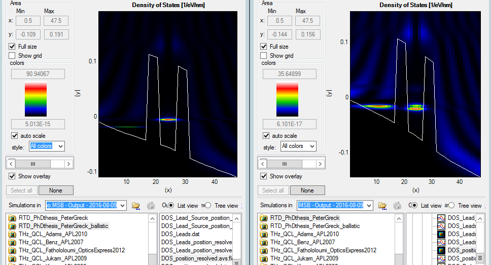
Figure 4.7.7 For the ballistic calculation (left figure), the quantum well state is aligned energetically with the chemical potential of the left contact (source). For the scattering calculation (right figure), the quantum well state is aligned energetically with the triangular quantum well state left of the barrier.
Electron density \(n(x,E)\) plots:
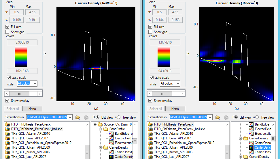
Figure 4.7.8 For the ballistic calculation (left figure), the quantum well state is aligned energetically with the chemical potential of the left contact (source). For the scattering calculation (right figure), the quantum well state is aligned energetically with the triangular quantum well state left of the barrier.
Current density \(j(x,E)\) plots:
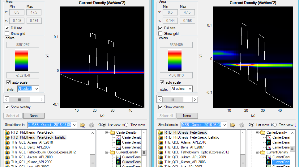
Figure 4.7.9 For the ballistic calculation (left figure), the quantum well state is aligned energetically with the chemical potential of the left contact (source). For the scattering calculation (right figure), the quantum well state is aligned energetically with the triangular quantum well state left of the barrier. On the right figure one can nicely see that the carriers that are injected from the left contact (source) scatter into the triangular quantum well state and then tunnel through the double barrier into the right contact (drain).
Further comments regarding the MSB input file
In order to calculate the current ballistically, we switched off the scattering by the following flag.
MSB_1Band{
   Core{
      BallisticCalculation = yes
   }
}
Please help us to improve our tutorial. If you have any questions or comments, create a ticket nextnano Help Center.