— FREE — Variables
Header
- Files for the tutorial located in nextnano++\examples\basics
basics_1D_variables.in
Introduction
This tutorial teaches how to use variables in the input file. Besides their advantages for the code, e.g. enhance flexibility, creating dependencies between parameters, etc., variables enable performing parameter sweeps in nextnano++. After completing this tutorial, you will know more about:
defining variables
common usage of variables in nextnano++
In this tutorial we want to create a GaAs/InAs/GaAs single quantum from tutorial 1 well once again, this time using variables.
Defining variables
 7# Independant variables
 8#----------------------
 9
10$device_start = 0.0              # device starts at x = 0.0 nm (DisplayUnit:nm)
11$device_length = 50.0            # device ranges from  $device_start to $device_start + $device_length (DisplayUnit:nm)
12$InAs_width = 20.0               # thickness of InAs layer (DisplayUnit:nm) (ListOfValues:5.0, 10.0, 20.0)
13
14$grid_spacing_fine = 0.5         # fine grid spacing value (DisplayUnit:nm)
15$grid_spacing_course = 2.0       # coarse grid spacing value (DisplayUnit:nm)
16
17# Derived variables
18#------------------
19
20$InAs_start = $device_start  + ( $device_length - $InAs_width )/2    # calculating start position of InAs layer (InAs layer should be centered around the middle of the device) (DisplayUnit:nm) (DoNotShowInUserInterface)
21$InAs_end = $device_start  + ( $device_length + $InAs_width )/2      # calculating end position of InAs layer (DisplayUnit:nm) (DoNotShowInUserInterface)
Variables start with the character “$” followed by their name. A good practice is place the variables at the beginning of the input file.
In the example we see one major application for variables in nextnano++, namely the structural design. Since we are now able to define dependencies between
parameters explicitly, three variables - $xmin, $device_length and $InAs_width - set up the complete device structure.
The comments (DisplayUnit: … ), (ListOfValues: … ) and (DoNotShowInUserInterface) are important for parameter sweeps which we will discuss later. The purpose of these three specifiers in particular are to display the unit of the variable in the sweep interface, to give a list of sweep values and to exclude a variable from the sweep interface.
Specifying the grid
37grid{ # this group is required in every input file
38    xgrid{                                      # grid in x direction
39        line{
40            pos = $device_start                 # assign start position of device (x=0.0 nm)
41            spacing = $grid_spacing_fine        # assign course grid spacing (4.0 nm)
42        }
43        line{
44            pos = $InAs_start                   # assign grid point at GaAs/InAs interface (20.0 nm)
45            spacing = $grid_spacing_course      # assign fine grid spacing (0.5 nm)
46        }
47        line{
48            pos = $InAs_start                   # assign grid point at InAs/GaAs interface (30.0 nm)
49            spacing = $grid_spacing_course      # assign fine grid spacing (0.5 nm)
50        }
51        line{
52            pos = $device_start+$device_length  # assign end position of device (x=50.0 nm)
53            spacing = $grid_spacing_fine        # assign course grid spacing (4.0 nm)
54        }
55    }
56}
The grid is now completely derived from the variables. Now, if some variables are changed, we ensure that the grid is adapted to the structure of the device.
Specifying the structure
59structure{
60    region{
61        binary{ name = GaAs }                   # GaAs region
62        contact{ name = whatever }              # contact definition
63        everywhere{}                            # region spreads over the complete device (from $device_start to $device_start+$device_length)
64    }
65    region{
66        binary{ name = InAs }                   # InAs region
67        line{ x = [ $InAs_start , $InAs_end ] } # derived position of InAs layer
68                                                # overwrites the previously defined GaAs region
69    }
70}
We assign the previously derived variables for the position of the InAs layer to the corresponding region.
Application: Performing a parameter sweep
For performing a parameter sweep, it was necessary to introduce variables. Now, we want to show how to sweep through the InAs layer thickness and then output the simulated energy profiles.
The first step is to initialize the sweep. Under the tab Template in nextnanomat we load the currently
opened input file by clicking ref: icon (Figure 2.4.21). Then we select list of values and the variable $InAs_width which should be swept.
Since we specified a list of values for $InAs_width in the input file, the list is automatically
inserted. Then we have to create the input files for each value in the list. By clicking create input file they are
added to the batch list.
The second step is to run all files from the batch list by pressing F10.
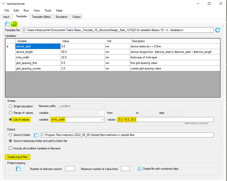
Figure 2.4.21 Screenshot showing nextnanomat interface to initialize the sweep:
load input file,
select variable and list of values for the sweep,
create new input files (saved to temporary folder)
After running the simulation you should find an output folder for every sweep value: basics_1D_variables_InAs_width_<SweepValue>.
Figure 2.4.22 shows the overlay of energy profiles from every sweep.
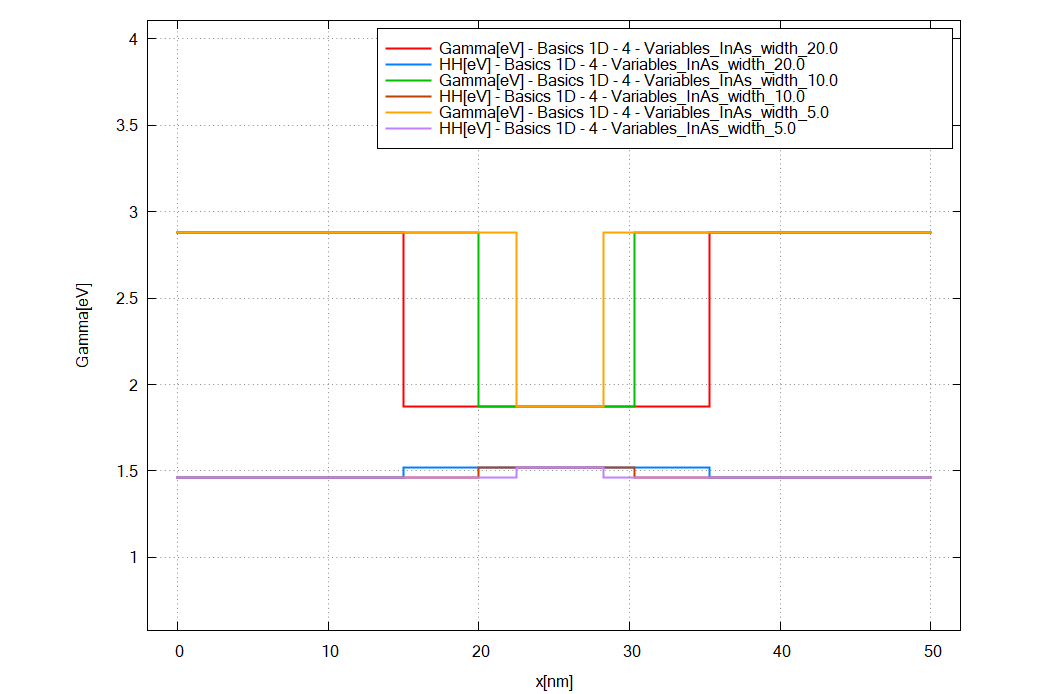
Figure 2.4.22 Overlay of energy profiles (conduction band at \(\Gamma\) and heavy hole valence band) corresponding to different InAs layer widths
Important things to remember
Variables are defined by “$” + “Name of variable”
Last update: 16/07/2024