

structure{ region{} } - shape objects#
Functionality
Every region needs to have a certain shape, which can be defined by several objects. It consists of a certain material and/or contact, and it can have a doping profile.
Any subsequently defined region overwrites previously defined ones in the overlapping area. For exclusive properties such as material and contact, this implies a substitution of the old value.
Concerning doping, the new profile is added to any previously defined one.
Geometric objects may also be defined such that they are partially, mostly, or completely outside of the simulation region. Only the parts of structures which are inside of the simulation region will be used, everything else is ignored.
The following structures are supported. These are put under structure{ region{} }.
Nested keywords
… for all simulations
Nested keywords
… for 1D simulations
… for 2D simulations
… for 3D simulations
everywhere{ }#
An entire simulation domain
line{}#
1D object. a line from start to end point along the specified direction
- Example
line{                               # 1D object
    x = [10.0, 20.0]            # a line from 10 nm to 20 nm along the x direction
}
rectangle{}#
2D object, a rectangle defined by two lines along the x and y directions

- Example
rectangle{                          # 2D object, a rectangle defined by two lines along the x and y directions
        x = [10.0, 20.0]            # a line from 10 nm to 20 nm along the x direction
        y = [ 0.0,  5.0]            # a line from  0 nm to  5 nm along the y dire
}
circle{}#
2D object, a circle is defined by its center and radius

- Example
circle{                                     # 2D object, a circle is defined by its center and radius
    center{ x = 10.5   y = 14.0 }           # same as for regular_polygon
    radius = 10.0                           # radius
}
trapezoid{}#
2D object e.g. a simple trapezoid along the x axis

- Example
trapezoid{                      # 2D object e.g. a simple trapezoid along the x axis
    base_x     = [ 5, 15]       # base line extends in x direction from 5 to 15 nm
    base_y     = [25, 25]       # base line has a constant y coordinate y = 25 nm
    top_x      = [ 8, 12]       # top line extends in x direction from 8 to 12 nm
    top_y      = [30, 30]       # top line has a constant y coordinate y = 30 nm
}
Note
Exactly one of the elements base_x and base_y has to be set by two equal numbers to define the base line.
The same holds for top_x and top_y to define the top line.
semiellipse{}#
2D object, e.g. a simple semiellipse along the x axis

- Example
semiellipse{                    # 2D object, e.g. a simple semiellipse along the x axis
    base_x     = [45, 55]       # extension of base plane in x direction, i.e. from 45 to 55 nm.
    base_y     = [ 5,  5]       # base line at y = 5 nm
    top        = [50, 15]       # top coordinate of the semiellipse (x,y) = (50,15) in units of [nm]
}
Note
Exactly one of the elements base_x, and base_y has to be set by two equal numbers to define the base line.
triangle{}#
2D object, a triangle defined by its 3 vertices

- Example
triangle{                           # 2D object, a triangle defined by its 3 vertices.
    vertex{ x = 10.5   y = 14.0 }   # a vertex P is defined by its x and y coordinates: P=(x,y).
    vertex{ x =  0.0   y =  0.0 }   #
    vertex{ x =  5.0   y = 10.0 }   #
}
polygon{}#
2D object, a polygon defined by its vertices. If the first and the last defined vertex are not identical, then they are joined with a line.

- Example
polygon{                            # 2D object, a polygon defined by its vertices. If the first and the last defined vertex are not identical, then they are joined with a line.
    vertex{ x = 10.5   y = 14.0 }   # a vertex P is defined by its x and y coordinates: P=(x,y). Multiple vertices can and must be defined for a polygon.
                                    # Vertices must be ordered either clockwise or counterclockwise, otherwise the behavior during structure generation will be undefined.
}
regular_polygon{}#
2D object, a polygon with equal angles and equal side lengths. It is defined by its center, one vertex and the number of facets.

- Example
regular_polygon{                    # 2D object, a polygon with equal angles and equal side lengths. It is defined by its center, one vertex and the number of facets.
    center{ x = 10.5   y = 14.0 }   # The center point M is defined by its x and y coordinates: M=(x,y).
    corner{ x = 20.0   y = 30.0 }   # A corner vertex P is defined by its x and y coordinates: P=(x,y). Only one corner must be specified. By modifying the corner coordinates the whole polygon can easily be rotated around its center.
    number_of_facets = 7            # number of facets (= number of vertices), must be >= 3
}
hexagon{}#
2D object, a polygon with equal angles and equal side lengths and 6 facets. It is defined by its center and one corner vertex.

- Example
hexagon{                            # 2D object, a polygon with equal angles and equal side lengths and 6 facets. It is defined by its center and one corner vertex.
    center{ x = 10.5   y = 14.0 }   # same as for regular_polygon
    corner{ x = 20.0   y = 30.0 }   # same as for regular_polygon
}
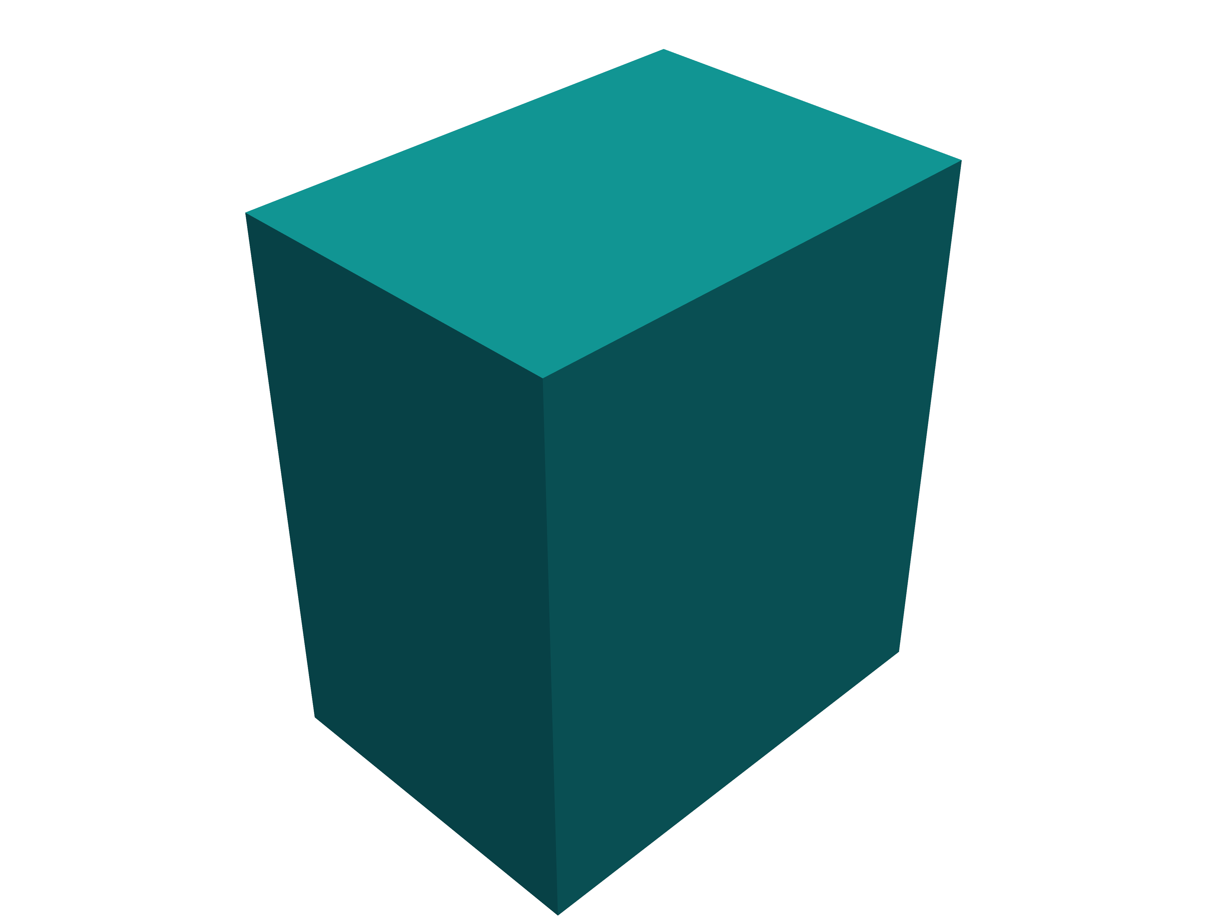
cuboid{}#
3D object, a cuboid defined by three lines along the x, y and z directions
- Example
cuboid{                         # 3D object, a cuboid defined by three lines along the x, y and z directions
    x = [10.0, 20.0]            # a line from 10 nm to 20 nm along the x direction
    y = [ 0.0,  5.0]            # a line from   0 nm to  5 nm along the y direction
    z = [ 0.0,  5.0]            # a line from   0 nm to  5 nm along the z direction
}
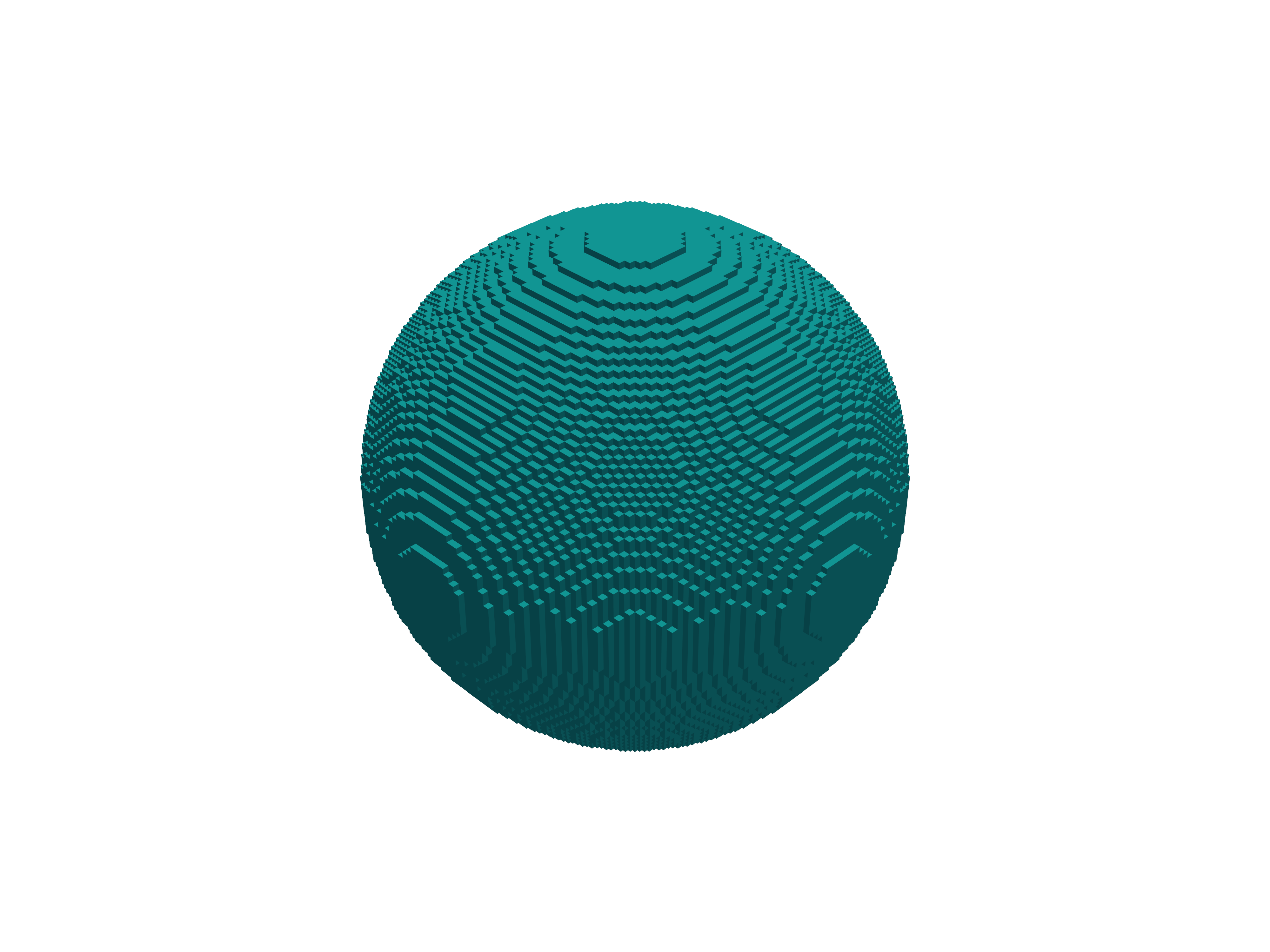
sphere{}#
3D object, a sphere is defined by its center and radius
- Example
sphere{                                     # 3D object, a sphere is defined by its center and radius
    center{ x = 10.5   y = 14.0   z = 1.0 } # similar as for circle
    radius = 10.0                           # radius
}
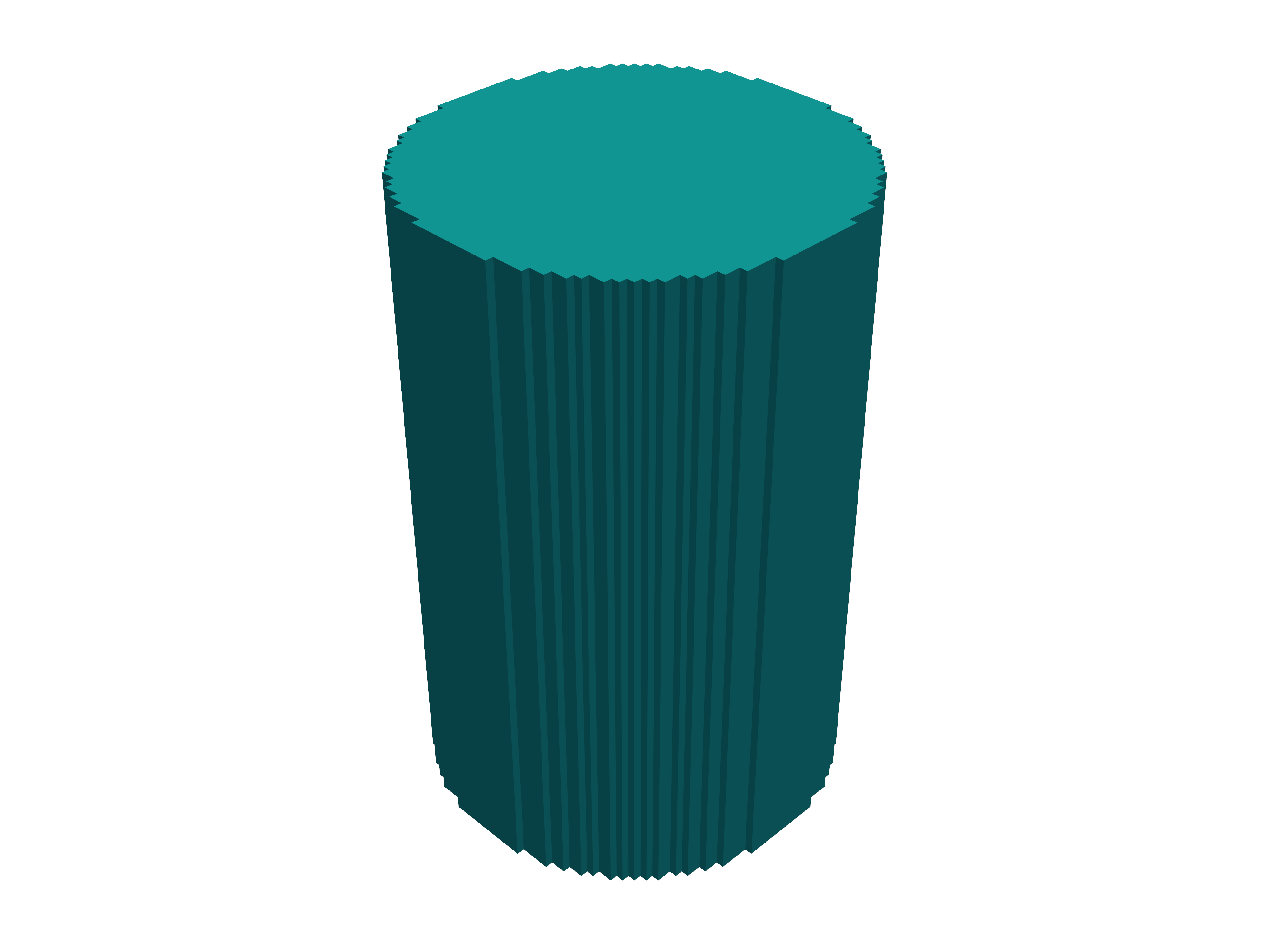
cylinder{}#
3D object, e.g. a cylinder with a freely oriented axis
- Example
cylinder{                             # 3D object, e.g. a cylinder with a freely oriented axis
    axis_start = [50.0, 50.0, 30.0]   # coordinates of starting point of cylinder axis
    axis_end   = [50.0, 50.0, 60.0]   # coordinates of ending point of cylinder axis
    radius     = 20.0                 # radius of cylinder
}
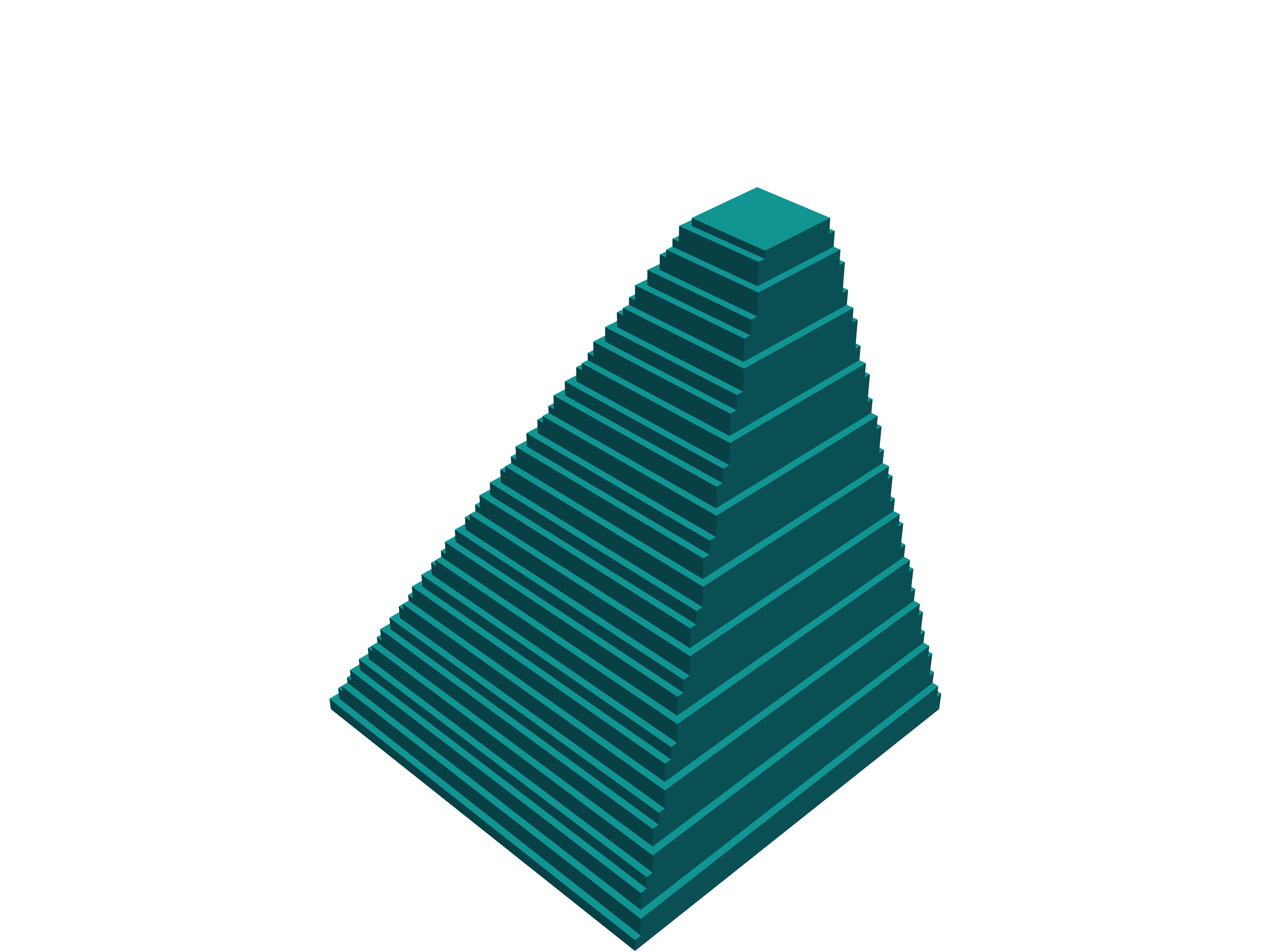
obelisk{}#
3D object, e.g. an obelisk parallel to the (x,y) plane with top below bottom
- Example
obelisk{                            # 3D object, e.g. an obelisk parallel to the (x,y) plane with top below bottom
    base_x     = [ 11, 19]          # extension of base plane in x direction, i.e. from 11 to 19 nm.
    base_y     = [ 9,  21]          # extension of base plane in y direction, i.e. from 9 to 21 nm.
    base_z     = [10, 10]           # base plane at z = 10 nm
    top_x      = [ 12, 18]          # extension of top plane in x direction, i.e. from 12 to 18 nm.
    top_y      = [ 11, 19]          # extension of top plane in y direction, i.e. from 11 to 19 nm.
    top_z      = [22, 22]           # top plane at z = 22 nm
}
Note
Exactly one of the elements base_x, base_y and base_z has to be set by two equal numbers to define the base plane.
The same holds for top_x, top_y and top_z to define the top line.
hexagon_obelisk{}#
3D object, an obelisk with its base and top planes given by hexagons
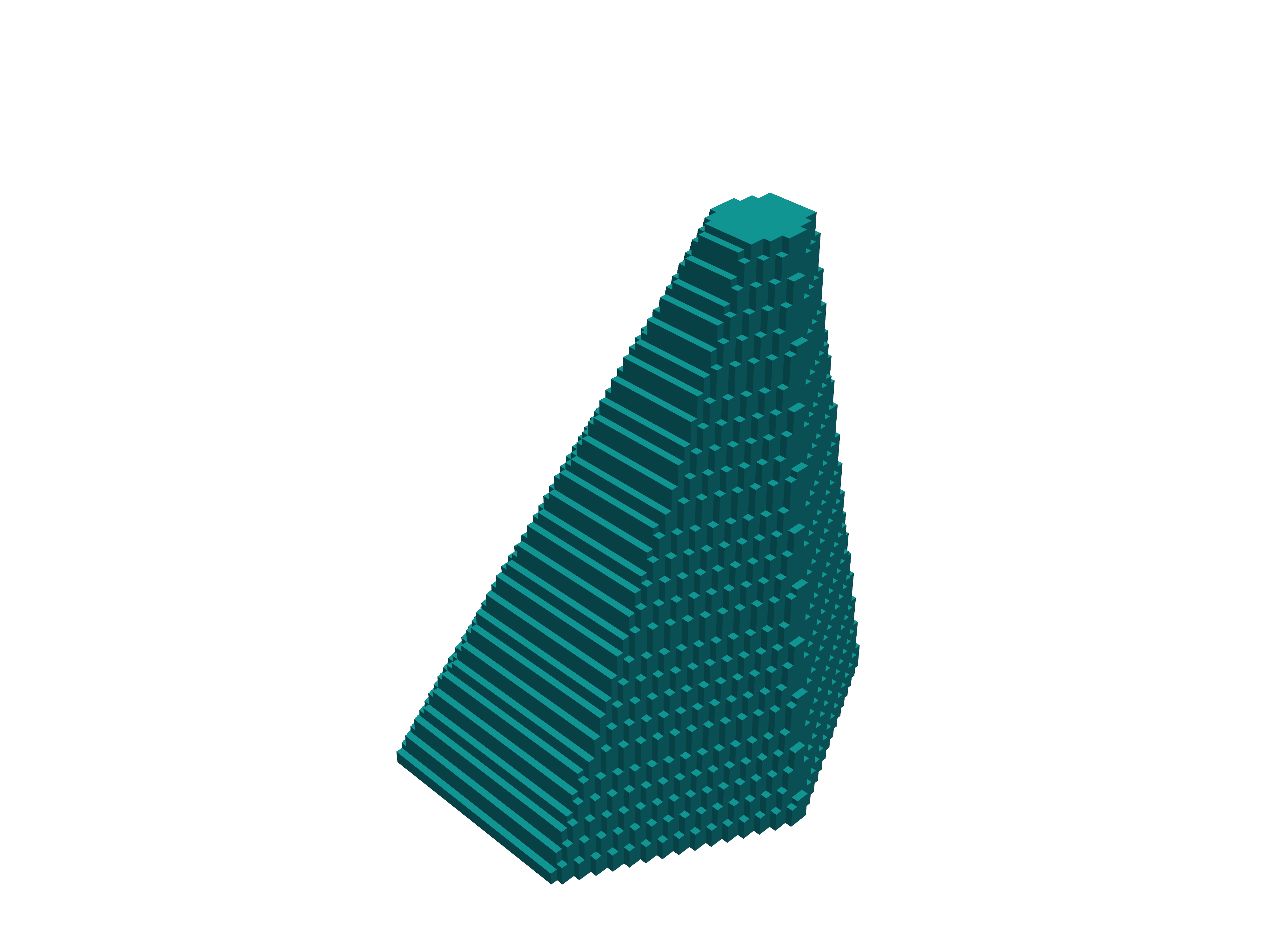
- Example
hexagon_obelisk{               # 3D object, an obelisk with its base and top planes given by hexagons
    ... (same as obelisk to define position, orientation and extension of object)
    permute    = yes/no         # (optional) switch between two possible orientations of the hexagon within the rectangularly defined planes
}
semiellipsoid{}#
3D object, e.g. a semiellipsoid parallel to the (y,z) plane with top below bottom
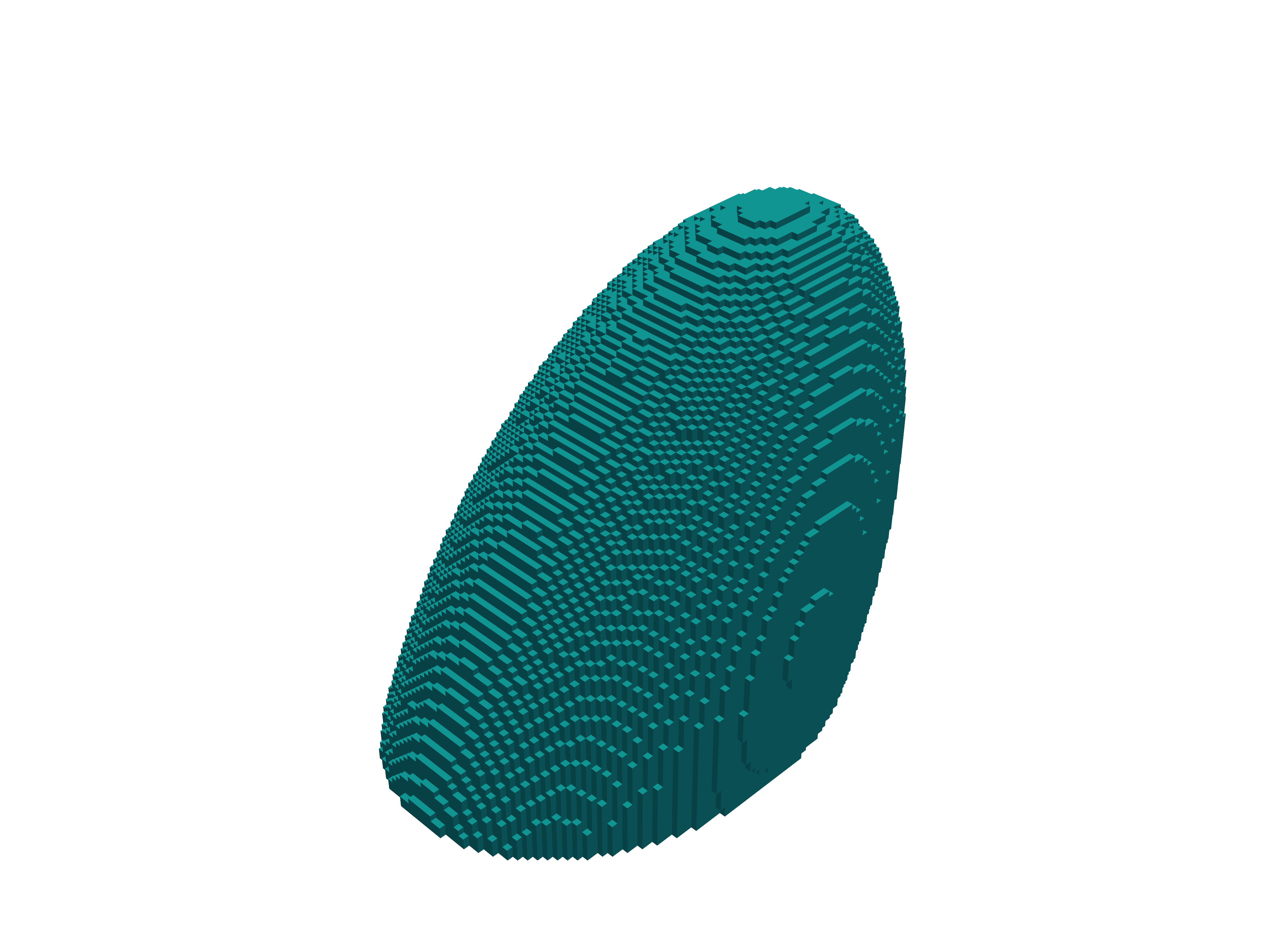
- Example
semiellipsoid{                      # 3D object, e.g. a semiellipsoid parallel to the (x, y) plane with top below bottom
    base_x     = [9, 21]            # extension of base plane in x direction, i.e. from 9 to 21 nm.
    base_y     = [11,  20]          # extension of base plane in y direction, i.e. from 11 to 20 nm.
    base_z     = [10, 10]           # base plane at z = 10 nm
    top        = [11, 15, 24]       # top coordinate of the semiellipsoid (x,y,z) = (11,15,24) in units of [nm]
}
Note
Exactly one of the elements base_x, base_y, and base_z has to be set by two equal numbers to define the base plane.
cone{}#
3D object, e.g. a cone parallel to the (x,z) plane
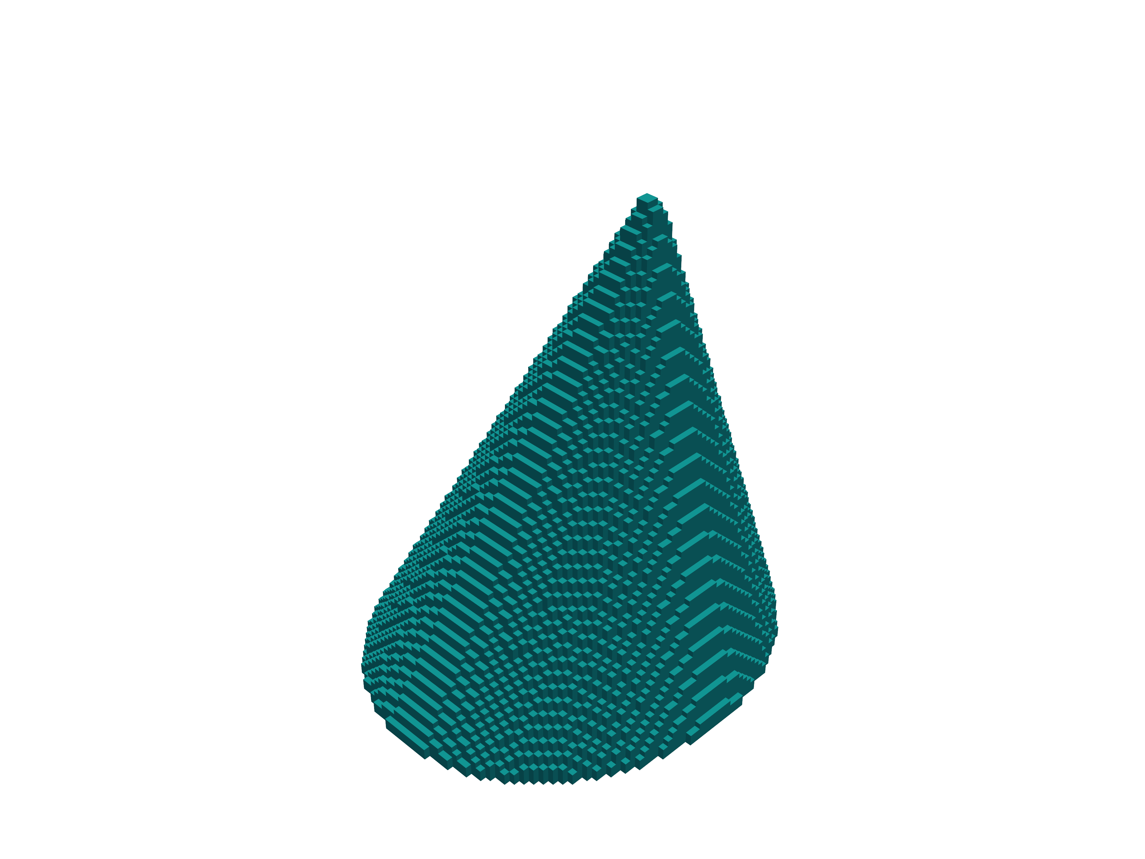
- Example
cone{                           # 3D object, e.g. a cone parallel to the (x,z) plane
    base_x     = [ 5, 20]       # extension of base plane in x direction, i.e. from 5 to 20 nm.
    base_y     = [20, 20]       # base plane at y = 20 nm
    base_z     = [ 7, 19]       # extension of base plane in z direction, i.e. from 7 to 19 nm.
    top        = [10, 30, 11]   # top coordinate of the cone (x,y,z) = (10,30,11) in units of [nm]
    diminution = 0.0            # (optional) minimum value is 0.0 (i.e. cone), maximum value is 1.0 (i.e. cylinder)
                                # diminution = 0.5 corresponds to "half diameter of base diameter", default is 0.0 (i.e. cone)
}
Note
Exactly one of the elements base_x, base_y, and base_z has to be set by two equal numbers to define the base plane.
polygonal_prism{}#
3D object (= 2D polygon with extension into the perpendicular direction; vertices define the circumference of the prism.)
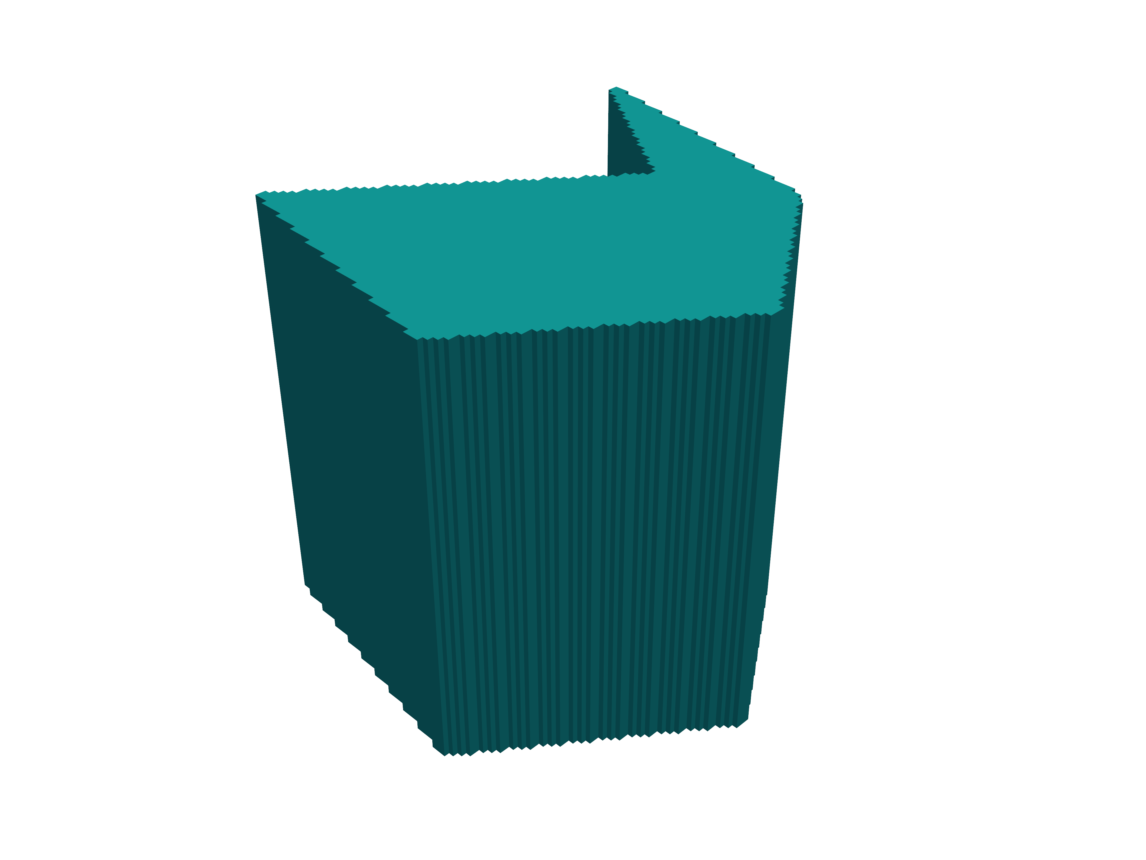
- Example
polygonal_prism{                    # 3D object (= 2D polygon with extension into the perpendicular direction; vertices define the circumference of the prism.)
    z = [0, 10]                     # define the extent in the desired height direction. Here: Height is defined with respect to z direction.
    vertex{ x = 10.5   y = 14.0 }   # a vertex P is defined by its x and y coordinates: P=(x,y). Multiple vertices can and must be defined for a polygon.
                                    # Vertices must be ordered either clockwise or counterclockwise, otherwise the behavior during structure generation will be undefined.
    axis = [0, 1, 1]                # (optional) inclination (shear) of prism structure
                                    # (Obviously, cyclic permutation of x, y, z are possible.)
}
regular_prism{}#
3D object (= 2D regular_polygon with extension into the perpendicular direction; center and/or corner define the circumference of the prism.)
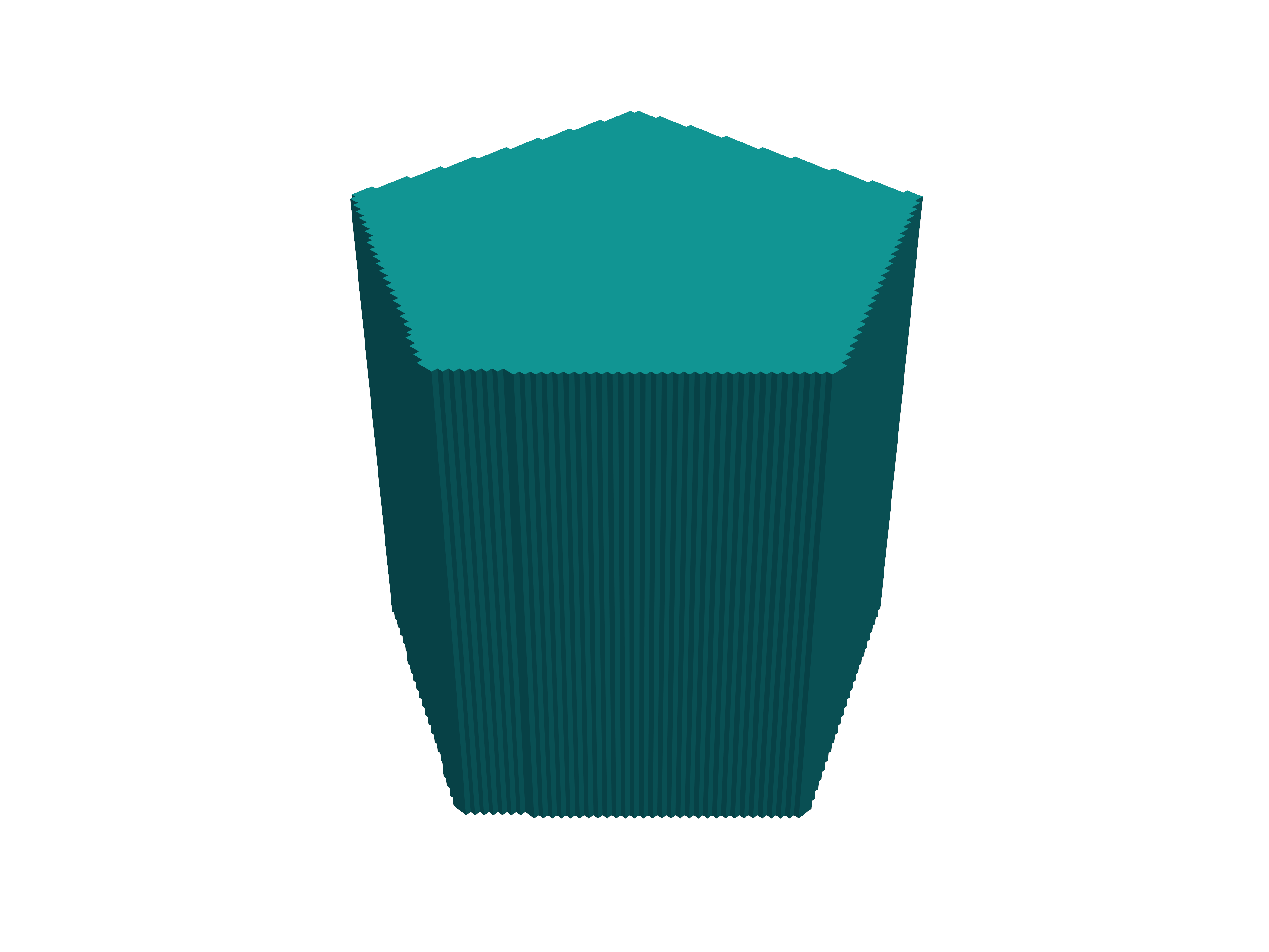
- Example
regular_prism{                      # 3D object (= 2D regular_polygon with extension into the perpendicular direction; center and/or corner define the circumference of the prism.)
    z = [0, 10]                     # define the extent in the desired height direction. Here: Height is defined with respect to z direction.
    center{ x = 10.5   y = 14.0 }   # The center point M is defined by its x and y coordinates: M=(x,y).
    corner{ x = 20.0   y = 30.0 }   # A corner vertex P is defined by its x and y coordinates: P=(x,y). Only one corner must be specified. By modifying the corner coordinates the whole polygon can easily be rotated around its center.
    number_of_side_facets = 7       # number of side facets (= number of vertices), must be >= 3
    axis = [0, 1, 1]                # (optional) inclination (shear) of prism structure
                                    # (Obviously, cyclic permutation of x, y, z are possible.)
}
hexagonal_prism{}#
3D object (= 2D hexagon with extension into the perpendicular direction; center and/or corner define the circumference of the prism.)
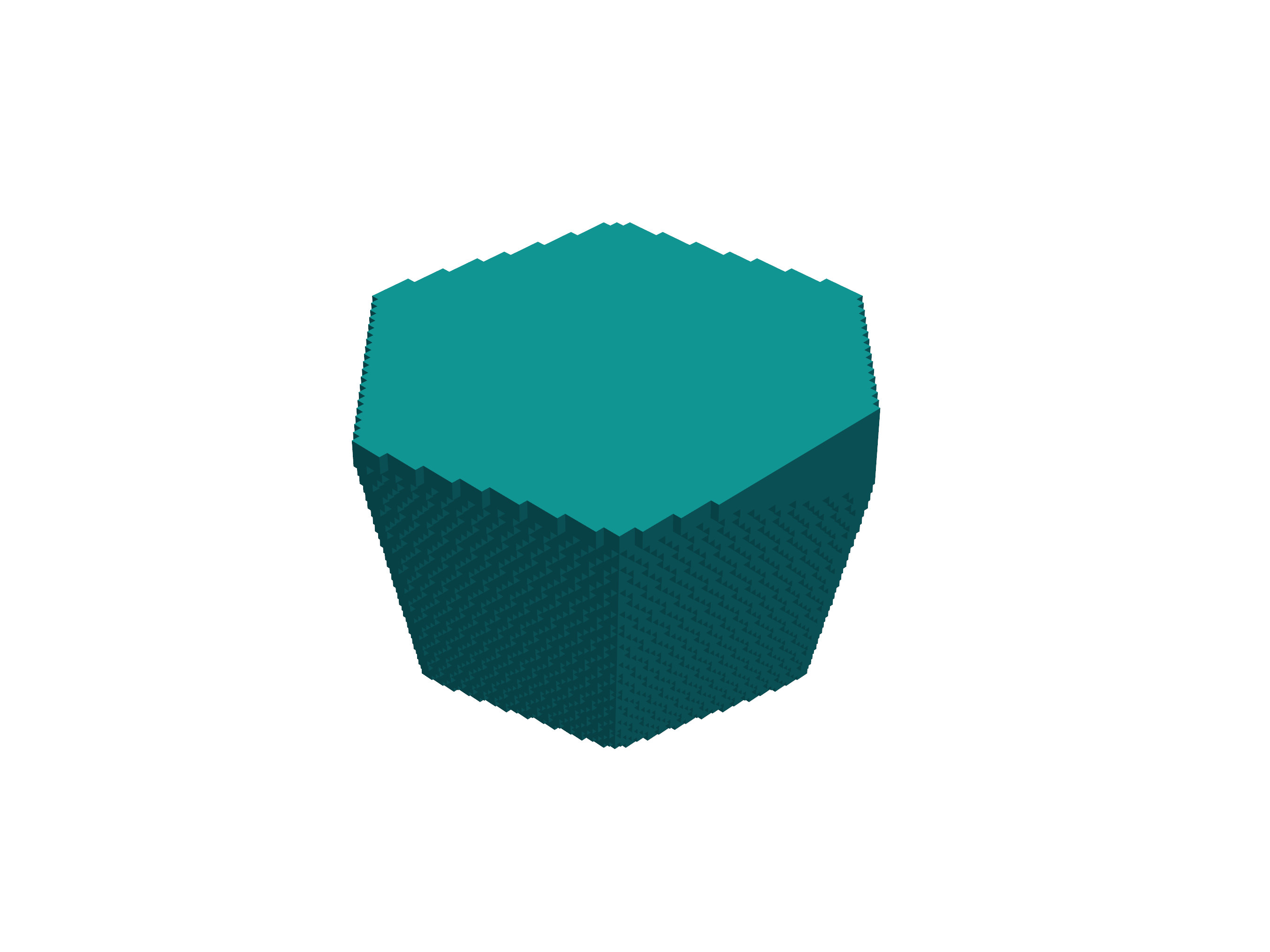
- Example
hexagonal_prism{                    # 3D object (= 2D hexagon with extension into the perpendicular direction; center and/or corner define the circumference of the prism.)
    z = [0, 10]                     # define the extent in the desired height direction. Here: Height is defined with respect to z direction.
    center{ x = 10.5   y = 14.0 }   # same as for regular_polygon
    corner{ x = 20.0   y = 30.0 }   # same as for regular_polygon
    axis = [0, 1, 1]                # (optional) inclination (shear) of prism structure
                                    # (Obviously, cyclic permutation of x, y, z are possible.)
}
Note
Per default, all prisms (polygonal_prism, regular_prism, hexagonal_prism) are assumed to extend along the respective layer thickness direction (i.e. normal to the defining coordinate plane). But, using the axis vector, an arbitrary axis (inclination) direction for the prism can be defined in the simulation system. The axis vector does not need to be normalized, however, its orientation defines which side of the prism layer is the base to be used as reference for the inclination.
For example,
regular_prism{
    z = [50, -70]                 # automatically reordered to [-70, 50]
    center{ x = 10   y = 10 }
    corner{ x = 30   y = 40 }
    number_of_side_facets = 8     # regular octagon wanted
    axis = [15 , 25 , 120]        # no normalization needed here
}
defines a regular octahedral prism extending primarily in the z direction (end surfaces are x-y planes at z = -70 and z = +50).
Since the axis points upwards in z direction (z = 120), the base surface to be taken as reference is the lower x-y plane at z = -70.
There, the octagon center is at { x = 10 y = 10 } with an octagon corner at { x = 30 y = 40 }
With the axis vector defined as above, we then find for the x-y plane at z = +50
the octagon center at
{ x = 10+15 y = 10+25 }andthe octagon corner at
{ x = 30+15 y = 40+25 }.
In analogy to polygon, we provide pyramidal structures.
polygonal_pyramid{}#
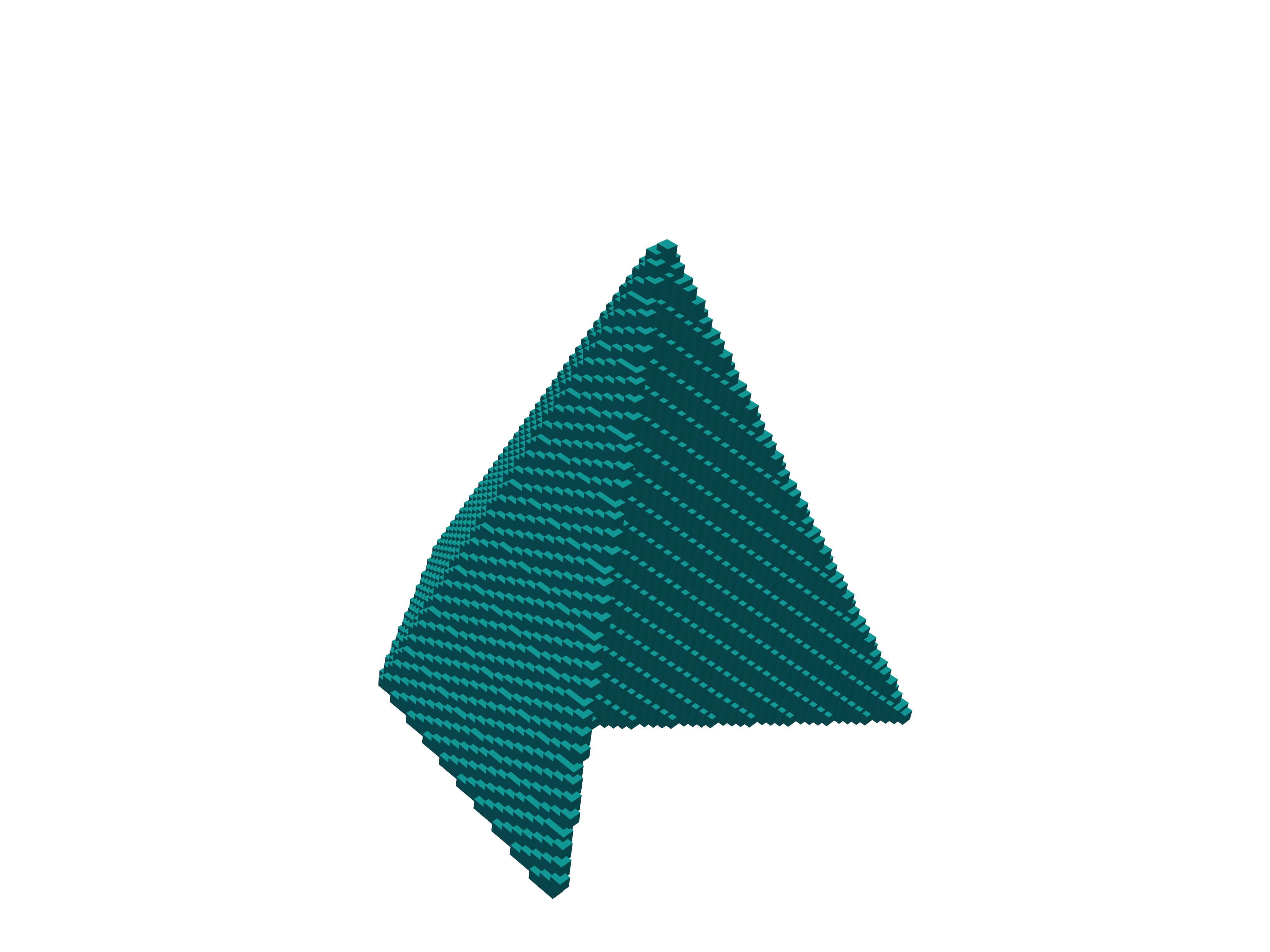
- Example
polygonal_pyramid{                  # 3D object
    z = [70, -70]                   # same as for polygonal_prism
    vertex{ x = 10.5   y = 14.0 }   # a vertex P is defined by its x and y coordinates: P=(x,y). Multiple vertices can and must be defined for a polygon.
                                    # Vertices must be ordered either clockwise or counterclockwise, otherwise the behavior during structure generation will be undefined.
    apex{   x = 10   y = 10   z = 120}
}
regular_pyramid{}#
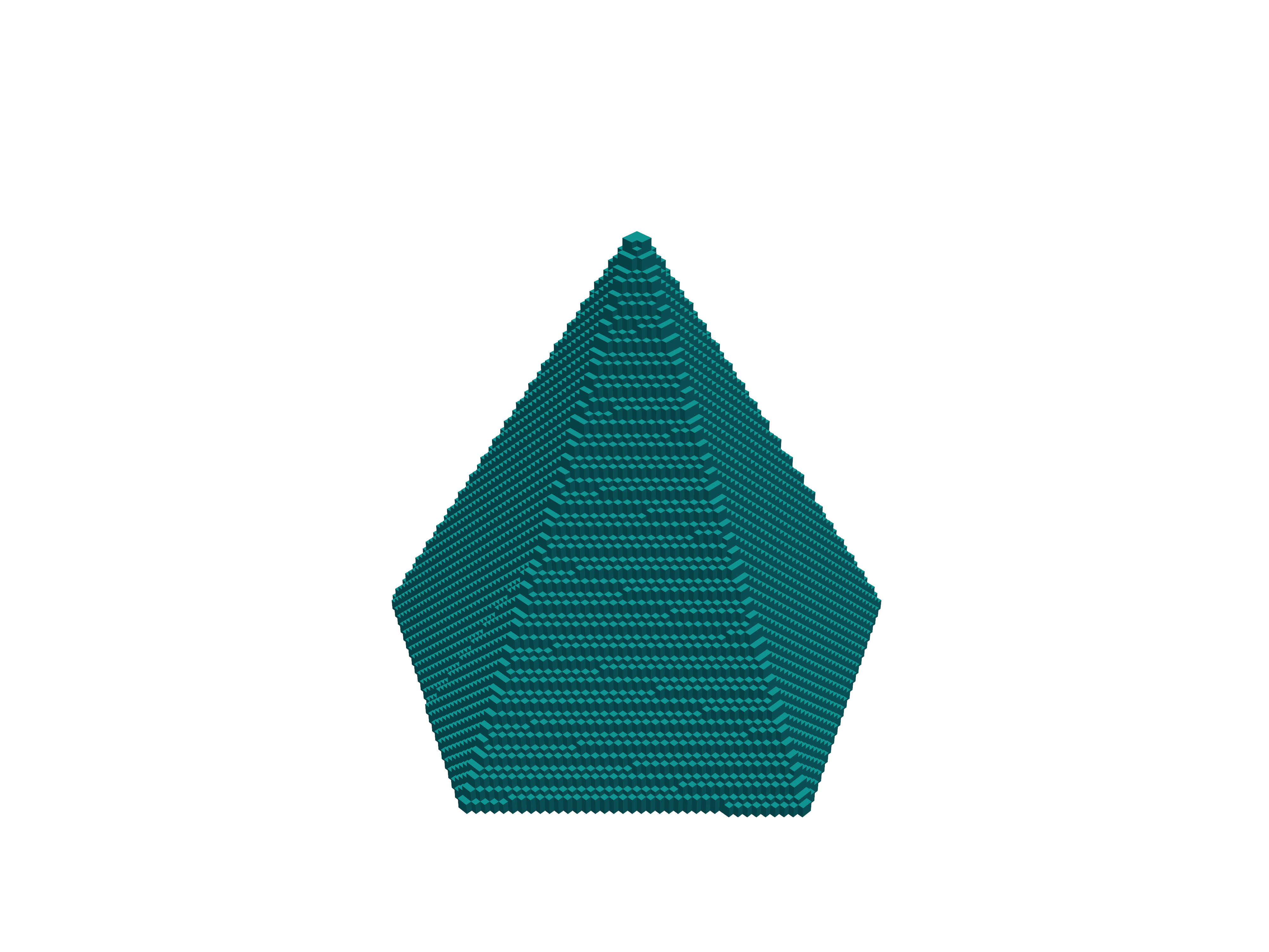
- Example
regular_pyramid{                  # 3D object
    z = [70, -70]                 # same as for regular_prism
    center{ x = 10   y = 10 }     # same as for regular_prism
    corner{ x = 70   y = 70 }     # same as for regular_prism
    number_of_side_facets = 8     # same as for regular_prism
    apex{   x = 10   y = 10   z = 120}
}
hexagonal_pyramid{}#
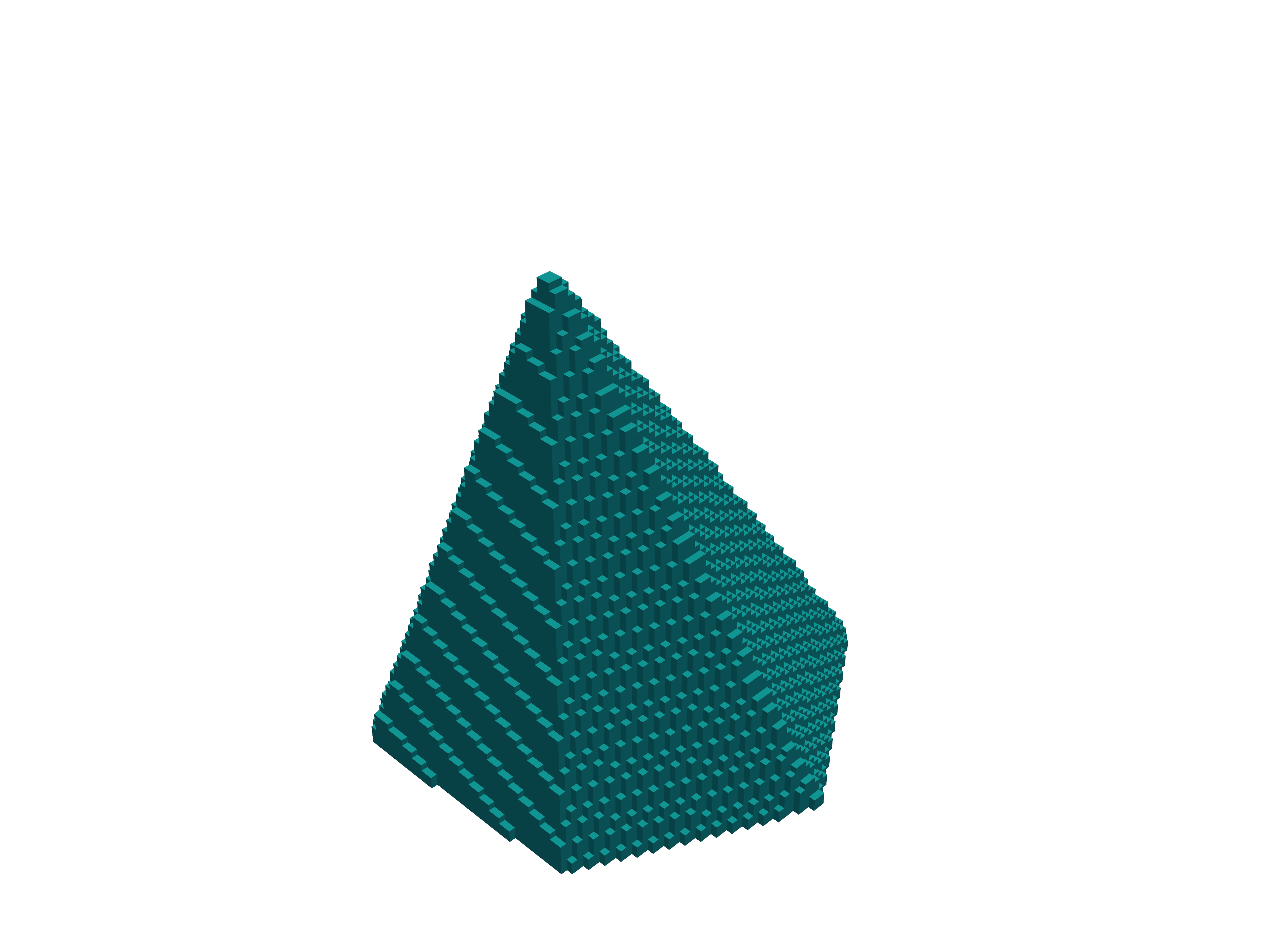
- Example
hexagonal_pyramid{                      # 3D object
    z = [70, -70]                       # same as for hexagonal_prism
    center{ x = 10   y = 10 }           # same as for hexagonal_prism
    corner{ x = 70   y = 70 }           # same as for hexagonal_prism
    apex{   x = 10   y = 10   z = 120}
}
Note
Similar to the prismatic structures, use x, y, and z at the beginning of the respective primitive to define the extent in the desired height direction, use vertex, center, and/or corner to define the circumference of the base of the pyramid, and apex to define the position of the apex of the pyramid.
Note that, for polygonal_pyramid (as for polygon), the vertices must be ordered either clockwise or counterclockwise, otherwise the behavior during structure generation will be undefined.
Also note that if the apex is located outside of the interval defined by x, y, or z at the beginning in the height direction, the pyramid will be truncated. Also, the pyramid will point upwards if the apex is above the center of said interval (and the lower plane is used as base), and will point downwards if the apex is below the center (and the upper plane is used as base). And in case a symmetric regular pyramid is desired, please make sure to laterally align the apex with the center point.
For example
regular_pyramid{
    z = [70, -70]
    center{ x = 10   y = 10 }
    corner{ x = 70   y = 70 }
    number_of_side_facets = 8
    apex{   x = 10   y = 10   z = 120}
}
defines a regular octahedral pyramid with base at z = -70, centered there at { x = 10 y = 10 } and a corner there at { x = 70 y = 70 }.
The apex of the pyramid would be at { x = 10 y = 10 z = 120}, making the structure rotationally symmetric, except that the pyramid is truncated at z = +70.
Thus, a rotationally symmetric truncated octahedral pyramid has been defined.
pyramid{}#
3D object, e.g. a pyramid with 4 freely defined corner points
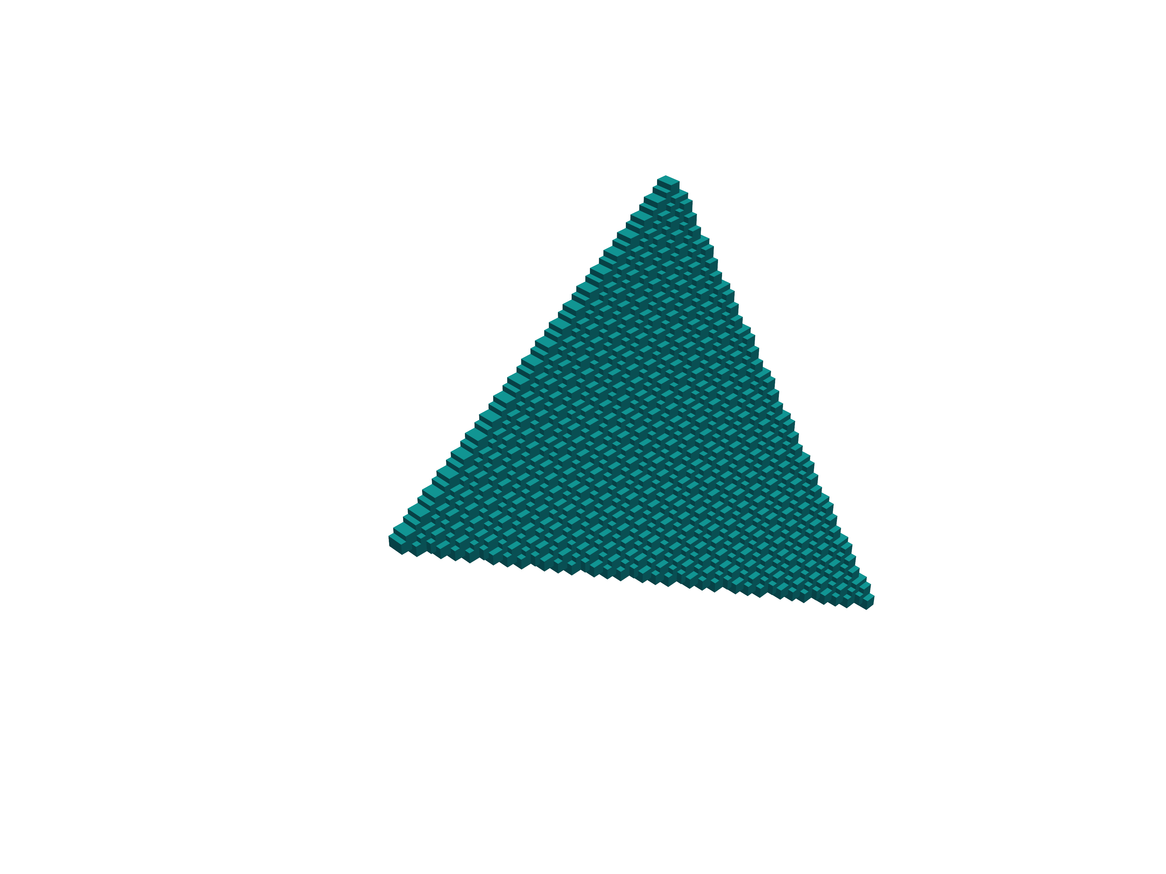
- Example
pyramid{                              # 3D object, e.g. a pyramid with 4 freely defined corner points
    point1 = [50.0, 20.0, 30.0]       # coordinates of first point of pyramid
    point2 = [50.0, 50.0, 80.0]       # coordinates of second point of pyramid
    point3 = [80.0, 50.0, 50.0]       # coordinates of third point of pyramid
    point4 = [50.0, 80.0, 30.0]       # coordinates of fourth point of pyramid
}
Note
When periodic{...} is used, objects extending over an edge of the simulation region will not automatically be continued on the opposite side.
If such objects are present in a periodic simulation, for each periodic coordinate direction (x, y or z), please either define a repetition
(using the size of the simulation region as shift with max = 1 and/or min = 1 as needed),
or extend an already present repetition to the edge of the simulation region (by increasing min and max as needed).