nextnano3 - Tutorial
next generation 3D nano device simulator
1D Tutorial
Strained 001 and 110 AlAs/AlGaAs QW - Crossover of ground states
Author:
Stefan Birner
If you want to obtain the input files that are used within this tutorial, please
check if you can find them in the installation directory.
If you cannot find them, please submit a
Support Ticket.
-> 1DAlAs_QW_110_DasguptaAPL2008.in

-> 1DAlAs_QW_110_DasguptaAPL2008_SchroedingerPoisson.in
Strained 001 and 110 AlAs/AlGaAs QW - Crossover of ground states
-> 1DAlAs_QW_110_DasguptaAPL2008.in
Note: Please also have a
look at this tutorial:
AlAs QW crossover I
This tutorial is based on the following paper:
Single valley high-mobility (110) AlAs quantum wells with anisotropic mass
S. Dasgupta, S. Birner, C. Knaak, M. Bichler, A. Fontcuberta i Morral, G.
Abstreiter, M. Grayson
submitted to Applied Physics Letters (2008)
We investigate the ground state energies of the X band edges in an AlAs
quantum well as a function of quantum well width.
The AlAs quantum well is embedded by Al0.45Ga0.55As
barriers that are strained with respect to the GaAs substrate.
The AlAs quantum well is assumed to be strained with respect to the GaAs
substrate.
For that reason, the three X band edges are split due to strain.
This splitting depends on the surface orientation of the quantum well plane,
which is determined by the orientation of the GaAs substrate, i.e. on the growth
direction.
We solve the single-band Schrödinger equation for the quantum well, i.e. for
each X band edge, taking into account automatically substrate orientation,
strain, deformation potentials, rotation of mass tensors and different effective
masses for the well and barrier materials.
Lattice constants
The 300 K lattice constants are given by:
AlAs: lattice-constants
	= 0.56611d0  0.56611d0  0.56611d0
	! [nm] 300 K

	GaAs: lattice-constants
	= 0.565325d0 0.565325d0 0.565325d0 ! [nm] 300 K
The temperature coefficients for the lattice constants are given by:
AlAs: lattice-constants-temp-coeff = 2.90d-6
	2.90d-6    2.90d-6    ! [nm/K]

	GaAs: lattice-constants-temp-coeff = 3.88d-6
	3.88d-6    3.88d-6    ! [nm/K]
This yields the following values for the lattice constants of GaAs and AlAs
at T = 4 K:
AlAs: 0.56611  nm +
	2.90d-6 nm/K (T - 300 K) = 0.562516
	nm

	GaAs: 0.565325 nm +
	3.88d-6 nm/K (T - 300 K) = 0.56417652 nm
The calculated lattice constants for Al0.45Ga0.55As and
GaAs can be found in the following output file:
lattice_constants1D.dat
Orientation
We distinguish between
- the crystal coordinate system (xcr = [100], ycr =
[010], z = [001]) and
[Dasgupta2] "crystal-basis x"
- the simulation coordinate system (x = [1-10], y = [110], z=[001]).
[Dasgupta2] "growth-basis a": a = [1-10],
b = [110], z=[001])
For (110) surface orientation we are using:
$domain-coordinates

   ...

   hkl-x-direction-zb     =
1 -1  0 !
for (110) surface ! along the [1-10] direction in
the crystal coordinate system
   hkl-y-direction-zb     =
1  1  0 !
 ! hkl-z-direction-zb     =
0  0  1 !
along the [001] direction in the crystal coordinate system
   growth-coordinate-axis = 0 1 0
! growth coordinate axis is y axis
Our growth direction is the y=[110] direction ([Dasgupta2]
b=[110] direction).
For (010) surface orientation we are using:
   hkl-x-direction-zb
= 1  0  0 !
for (010) surface !
along the [100] direction in the crystal coordinate system
hkl-y-direction-zb = 0 1 0 !
 ! hkl-z-direction-zb
= 0  0  1 !
along the [001] direction in the
crystal coordinate system
Note: For (010) surface orientation, both crystal and simulation
coordinate systems are identical.
Strain
AlAs is strained biaxially with respect to the GaAs substrate's lattice
constant, and is thus subject to a compressive strain.
The elastic constants of AlAs are given by:
 elastic-constants = 125.0d0 53.4d0 54.2d0
! [GPa] c11,c12,c44
The strain tensor components are thus given by:
Biaxial strain (in plane of interface, i.e. in (x,z) plane):
For (110) and (010) surface
orientation:
AlAs: e|| = exx,sim = ezz,sim = ( asubstrate
- alayer ) / alayer = ( aGaAs - aAlAs
) / aAlAs = -0.00190195 (-0.19 % lattice mismatch)
Uniaxial strain (perpendicular to interface, i.e. along y
direction):
For (110) surface orientation:
AlAs: e_|_ = eyy,sim = - D110 e||
= - (c11+3c12-2c44) / (c11+c12+2c44)
e|| = +0.0011725 (+0.12 % lattice mismatch)
[D110 = 0.616457461]
For (010) surface orientation:
AlAs: e_|_ = eyy
= - D010 e|| = - 2 (c12/c11)
e|| = +0.001625 (+0.16 % lattice mismatch)
[D010 = 0.8544]
For the (110) orientation, the hydrostatic strain is given by:
ehydro = Tr(eij) = exx,sim + eyy,sim
+ ezz,sim = 2 e|| + e_|_ = -0.00263
(-0.26 % compressive strain, decrease in volume) = exx,cr + eyy,cr
+ ezz,cr
For the (010) orientation, the hydrostatic strain is given
by:
ehydro = Tr(eij) = exx
+ eyy + ezz
= 2 e|| + e_|_ = -0.00218 (-0.22 % compressive
strain, decrease in volume)
The off-diagonal strain tensor components are zero for both orientations with
respect to the simulation coordinate system, i.e. the strain
tensor is diagonal.
However, the strain tensor with respect to the crystal coordinate
system has a nonzero offdiagonal component for the (110) surface
orientation.
exx,cr = -0.00036474 (-0.04 % lattice mismatch)
eyy,cr = -0.00036474 (-0.04 % lattice mismatch)
ezz,cr = -0.00190195 (-0.19 % lattice mismatch)
exy,cr = 0.00153721 (-0.15 % lattice mismatch)
exz,cr = 0
eyz,cr = 0
The values for exx,cr and eyy,cr can also be obtained
by rotating the strain tensor (see [Dasgupta2]).
For (110) surface orientation it holds:
exx,cr = eyy,cr = ( e|| + e_|_ ) / 2
= -0.00036474 (-0.04 % lattice mismatch)
ezz,cr = ezz,sim = e||
= -0.00190195 (-0.19 % lattice mismatch)
The calculated strain tensor components (including hydrostatic strain) can be
found in the following files:
- strain1/strain_cr1D.dat - strain tensor
components with respect to the crystal coordinate system
- strain1/strain_sim1D.dat - strain tensor components
with respect to the simulation coordinate system
(For (010) surface orientation, both files are identical.)
X conduction band edges: Shift and splitting due to strain (deformation
potential)
The deformation potential for the X conduction band edge in AlAs is Xi = 6.11
eV.
   uniax-cb-deformation-potentials = 0d0
...d0 6.11d0 ! [eV] Gamma,L,X
There are three conduction band edges at the X points:
- EX,x : longitudinal mass oriented along x=[100] direction
- EX,y : longitudinal mass oriented along y=[010] direction
- EX,z : longitudinal mass oriented along z=[001] direction
The X conduction band edges shift as follows:
- (110) surface orientation:
Delta EX,x = Xi exx,cr = 6.11 eV * (-0.00036474) =
-2.22 meV
Delta EX,y = Xi exx,cr = 6.11 eV * (-0.00036474) =
-2.22 meV
Delta EX,z = Xi exx,cr = 6.11 eV * (-0.00190195) =
-11.62 meV
==> The X conduction band edge where the longitudinal mass is
oriented along the z=[001] orientation is the lowest in energy.
The other two bands have equal energy. Thus they are double-degenerate and
separated by 9.4 meV from the single-degenerate band.
- (010) surface orientation:
Delta EX,x = Xi exx,cr = 6.11 eV * (-0.00190195) =
-11.62 meV
Delta EX,y = Xi exx,cr = 6.11 eV * (+0.001625)
= +9.93 meV
Delta EX,z = Xi exx,cr = 6.11 eV * (-0.00190195) =
-11.62 meV
==> The X conduction band edges where the longitudinal masses
are oriented along the x=[100] or z=[001] orientation are the lowest in
energy.
These two bands have equal energy. Thus they are double-degenerate.
The single-degenerate band where the londitudinal mass is oriented parallel
to the growth direction y=[010] is separated by 21.6 meV from the
double-degenerate bands.
Single-band effective mass tensors for the X valleys
The mass tensors for the X valleys are ellipsoids characterized by a
longitudinal and two transverse masses.
For AlAs we use the following parameters.
 conduction-band-masses = ...
...    ...
! [m0] Gamma  m  m  m
(isotropic)
...    ...    ...
   ! [m0] L      ml mt
mt
1.1d0  0.2d0  0.2d0  ! [Dasgupta2] !
[m0] X      ml mt mt
- mX,x : longitudinal mass oriented along x=[100] direction
- mX,y : longitudinal mass oriented along y=[010] direction
- mX,z : longitudinal mass oriented along z=[001] direction
To discretize the Schrödinger equation along the growth direction, it is
necessary to rotate the inverse mass tensors into the simulation coordinate
system (see [Dasgupta2]).
For (110) surface orientation, the inverse mass tensors with respect to the
simulation coordinate system are given as follows
- mX,x : longitudinal mass oriented along x=[100] direction
            (
	1/md    1/mf     0
	)   (1/0.3385   1/0.4889   0
	)

	mX,x,simij-1 = (  1/mf
	 1/md     0    ) =
	(1/0.4889   1/0.3385
	0    )

            (
	0      1/mf    1/mt
	)   (  0
	0      1/0.2  )
- mX,y : longitudinal mass oriented along y=[010] direction
            (
	1/md   -1/mf    0
	)   ( 1/0.3385 -1/0.4889   0    )

	mX,y,simij-1 = ( -1/mf
	1/md    0    ) = (-1/0.4889
	1/0.3385   0
	)

            (
	0       1/mf   1/mt
	)   (   0
	0      1/0.2  )
- mX,z : longitudinal mass oriented along z=[001] direction
(unaffected by rotation!)
            (
	1/mt     0     0
	)   (  1/0.2       0
	0    )

	mX,z,simij-1 = (   0
	  1/mt    0     ) =
	(    0
	1/0.2      0
	)

            (
	0       0     1/ml
	)   (    0
	0      1/1.1  )
where md=2(mlmt)/(mt+ml)=0.3385[m0]
and mf=2(mlmt)/(mt-ml)=0.4889[m0].
The mass tensor components 1/myy
indicated in red are the ones the enter the discretized Schrödinger
equation.
Remember: The growth direction is along the y direction
in the simulation coordinate system (i.e. along the [110] direction in the
crystal coordinate system).
For (010) surface orientation, no rotation is necessary, so the mass tensors
are diagonal and given by:
- mX,x : longitudinal mass oriented along x=[100] direction
         ( 1/ml
	0     0   )   ( 1/1.1   0
	0   )

	mX,xij-1 = (  0
	1/mt   0   ) = (  0
	 1/0.2   0   )

         (  0
	 0    1/mt )   (  0
	1/0.2 )
- mX,y : longitudinal mass oriented along y=[010] direction
         ( 1/mt
	0     0   )   ( 1/0.2   0
	0   )

	mX,yij-1 = (  0
	1/ml   0   ) = (  0
	 1/1.1   0   )

         (  0
	 0    1/mt )   (  0
	1/0.2 )
- mX,z : longitudinal mass oriented along z=[001] direction
         ( 1/mt
	0     0   )   ( 1/0.2   0
	0   )

	mX,zij-1 = (  0
	1/mt   0   ) = (  0
	 1/0.2   0   )

         (  0
	 0    1/ml )   (  0
	1/1.1 )
The calculated inverse mass tensor components can be found in the
following files:
- Schroedinger_1band/mass_tensor1D_cb003_qc001_sg001_deg001.dat -
contains mX,x,sim and mX,y,sim
for (110) surface orientation
mX,x
and mX,z for
(010) surface orientation
- Schroedinger_1band/mass_tensor1D_cb003_qc001_sg002_deg001.dat -
mX,z,sim
for (110) surface orientation
contains mX,y
for (010) surface orientation
Cross-over width Wc
The following figures show the calculated ground state energies of the two X
valleys.
From these figures one can extract the cross-over width Wc for the
(110) and the (010) strained AlAs QW.
The experimentally observed cross-over is 5.5 nm for the (010) QW.
For (110) strained AlAs QWs, our calculations of strain and quantum confinement
predict anisotropic-mass valley occupancy for well widths greater than 5.3 nm.
Below this, double-valley occupation is predicted.
The dashed, grey lines show the calculated ground state energies for the
infinite barrier model (analytical model). In that case, the cross-over width is
greatly overestimated.
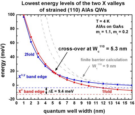 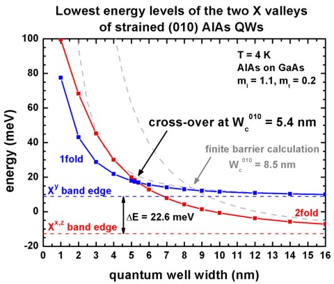
The respective eigenvalues can be found in these files:
  - Schroedinger_1band/ev1D_cb003_qc001_sg001_deg001_dir_Kx001_Ky001_Kz001.dat
-
(2fold degenerate)
  - Schroedinger_1band/ev1D_cb003_qc001_sg002_deg001_dir_Kx001_Ky001_Kz001.dat
-
(1fold degenerate)
Information about the numbering and the degeneracy of the Schrödinger equations
can be found in this file:
- Schroedinger_1band/sg_info.txt
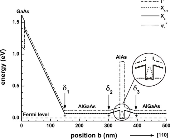
Strained 001 and 110 AlAs/AlGaAs QW - self-consistent Schrödinger-Poisson
calculation
-> 1DAlAs_QW_110_DasguptaAPL2008_SchroedingerPoisson.in
The following figure shows the self-consistently calculated conduction band
profile of the (110) sample as presented schematically in Fig. 1 of the paper by
Dasgupta et al. [Dasgupta2].
Three conduction band edges are shown:
- The Gamma conduction band (dashed-dotted line) is the highest in energy for
AlAs and Al0.45Ga0.55As, but the lowest for GaAs.
- The X conduction bands are split due to strain.
The Xz condution band edge is the lowest in energy where the
longitudinal mass is oriented along the z=[001] direction.
The growth direction is along y=[110].
The inset shows the square of the ground state wave function of the 15 nm wide,
strained AlAs quantum well.
This band structure has been obtained by solving self-consistently the
Schrödinger and the Poisson equation.
|